The contents of this guide work for version 4.19 of the Unreal Engine.
Optimization Viewmodes
You can change the way in which the scene is rendered when editing the project by changing the View Mode within the scene view port. Under this tab is the Optimization Viewmodes section; each of these views will help to identify certain optimizations that you can make. We will go over them in the order that they appear.

Figure 1: Finding the selection of optimization viewmodes.
This documentation doesn’t cover the Texture Streaming Accuracy portion of the Optimization Viewmodes, as they are more relevant to the creation of 3D models, but for information on what they show see Epic's documentation on texture streaming.
Light Complexity
The Light Complexity view shows us how our scene is being lit by our lights, the influence area of those lights, and how much cost to performance they can infer throughout the scene.
When we add a point light to the center of the scene, we can see the influence this light has on the complexity of the lighting in the scene.
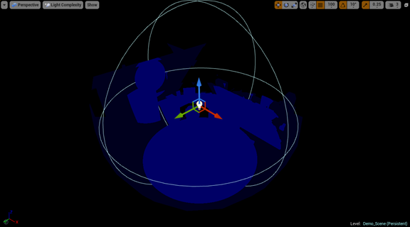
Figure 2: Single point light complexity.
If we create more point lights in the same area, we begin to see the cost of the overlapping through the visualizer. As more and more lights begin to overlap, the influenced areas will become red, then white.

Figure 3: Light Complexity of multiple point light sources.
The performance hit comes from each pixel in the overlap needing to be shaded by multiple sources. The cost of this on static lights is primarily a hit on the time it takes to bake the lighting of the scene, but when using moveable or stationary lighting the cost of dynamic lighting and shadows is increased.
To reduce the impact on scene performance, lights that cause overlap should be removed, switched to static, or their position and influence should be adjusted.

Figure 4: Lesser complexity by adjusting light radius.
Lightmap Density
The density of the lightmap for objects in your scene shows the texel density of the lighting effects that will be placed on those objects. For the viewport visuals, the greener the color-coded shade, the better the texel density of the lightmap for the object; while blue is less dense and red is denser. Because each lightmap is a texture, your texture streaming budget can be quickly used up if the number of objects in your scene goes up, or you use higher lightmap resolutions to increase the visual fidelity of the render.
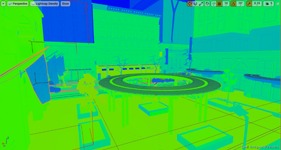
Figure 5: Scene view of lightmap density.
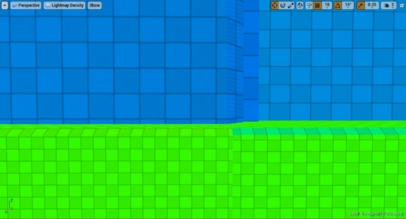
Figure 6: Up close view of different lightmap densities.
To change the lightmap density for any object in your scene, adjust the Overridden Light Map Resolution value (default of 64) to another that better fits the texel density of that object. As with other textures, sticking to powers of two (2, 4, 8, 16, 32, 64, and so on) will reduce wasted rendering.

Figure 7: Overridden Light Map Resolution.
Below, we can see a streetlight in the scene with the default lightmap resolution of 64. When its value is switched to 16, we see its color change from red to green; a better density, and cheaper lightmap for streaming.
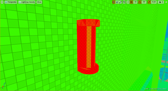
Figure 8: Object with a dense lightmap.

Figure 9: Same object with an optimal lightmap density.
Stationary Light Overlap
In the Unreal* Engine (UE) the stationary light plays a unique role in the development process. However, there is a limit to the number of stationary lights that may overlap, and going over that limit causes a hit on performance.

Figure 10: Collection of stationary lights and their overlaps.
When more than four stationary lights overlap, any additional stationary lights are forced to work as moveable lights, increasing in the performance requirement of each additional light. If we switch all the lights to be stationary we can see their influence over each other. The lighter the green, the fewer overlaps.

Figure 11: Stationary lights with too many overlaps.
After four overlaps the color changes to red. Any light involved in the red overlap will be rendered as a moveable light; displayed as a red X over the light’s billboard. To fix this issue, some of the offending lights must be removed, switched to static, or have their influence area reduced or moved.

Figure 12: Stationary lights crossed out, showing that they will be used as moveable lights instead.
Shader Complexity (& Quads)
This view allows you to see the number of shaders being calculated per pixel in your current view, with green being the lowest, and red and white being the highest (most expensive).
If we look at Robo Recall*, we see that the shader complexity of the whole scene is relatively light, with most of the cost going into the street around the city. Epic Games* made a large effort to reduce their shader complex to help hit their 90 frames per second goal for the VR title.
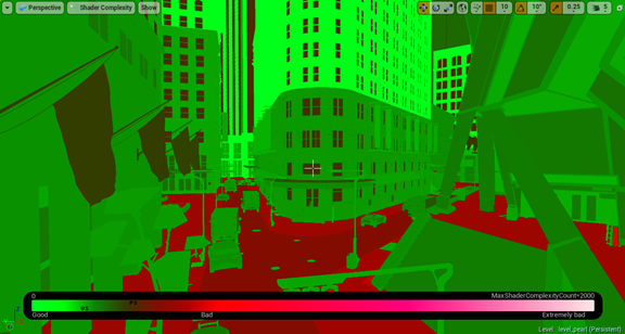
Figure 13: View of a scene with an optimized shaders.
However, looking a forest scene, we see that the shader complexity of the trees and their leaves is ridiculously high and unoptimized.
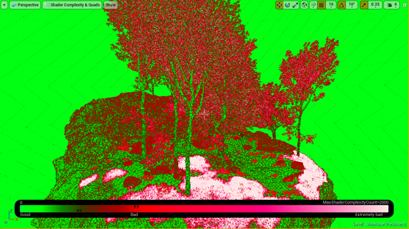
Figure 14: View of a scene with a large number of complex shaders.
To reduce the complexity of your shaders, the number of materials and the number of texture lookups within those materials needs to be reduced.
In addition, one of the biggest hits to performance with shader complexity comes from opacity, a main component of foliage and particle systems, and the reason the trees have such a high complexity.

Figure 15: Up close view of how transparencies affect shader complexity.
To reduce the number of opacity materials in your scene, you can design around it (Robo Recall has trees that are solar panel towers shaped to look like trees) or use level of detail (LOD) for your foliage and particles to reduce the number of meshes with opacity at a distance, a problem that unfortunately needs to be thought about early in development, or made up for with model production later in the project’s timeline.
Quad Overdraw
When multiple polygons are all overlapping and being rendered within the same quad on the graphics processing unit, the performance of the scene will suffer as these renders are calculated and then unused.
This issue is caused by the complexity of the meshes and the distance they are from the camera; the smaller the visible triangles of a mesh, the more are within a quad. If we look at the two pictures we see Robo Recall, with some overdraw on the edges of models and at a distance, and our forest scene, where there is a large amount of overdraw occurring within the trees around the whole forest. As with shader complexity, opacity is a major performance hit and causes a lot of overdraw.
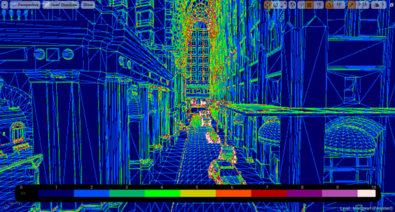
Figure 16: Scene view of quad-overdraw.
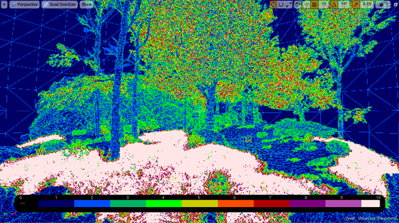
Figure 17: Scene view of a large amount of quad-overdraw.
To reduce the amount of overdraw, use LODs to reduce the poly count of models at a distance, and reduce transparencies in particle systems and foliage.
LOD Coloration
Knowing when your LODs switch is important for the visuals of your game, and the LOD coloration view gives you that information. LODs are crucial to optimizing any title, as they save on rendering details that cannot be seen from a distance and the triangle count of your models. Along with what was previously mentioned, LODs also help with quad overdraw and shader complexity performance issues.
Adding LODs can be done with modeling software or by using auto LOD generation (UE 4.12+), and the switch distance can be adjusted to work for your scene.
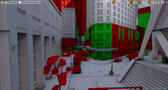
Figure 18: Scene view of level of details.
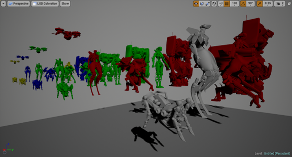
Figure 19: Skeletal mesh lineup of LODs.