Abstract
In this white paper we disclose the new Variable Rate Shading (VRS) hardware capability. Originally presented at High-Performance Graphics in 2014 as a new rendering algorithm we called Coarse Pixel Shading, the 11th Generation Intel® Processor Graphics marks our first public realization of this new capability, showing how to decouple shading and visibility to improve performance and maximize the user experience by spending time shading the pixels that matter the most. We describe how to use VRS in your application and propose a few directions of how you may want to take advantage of the new Variable Rate Shading API that is part of Microsoft DirectX* 12 on Windows* 19H1. As a companion to this article we also provide a VRS Tier 1 functional code sample to show the steps to engage VRS in your application and provide references for additional technical details.
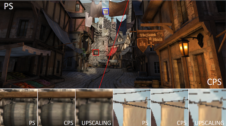
Figure 1. The canonical Citadel 1 image rendered at 2560 x 1440 with 1x1 pixel rate on the left and using variable rate shading at a 2x2 rate on the right. While VRS reduces the number of shader invocations, there is almost no perceivable difference on a high pixel density display. An upscaled image with no anti-aliasing applied is also shown for comparison rendered at 1280x720. Reprinted with permission from Vaidyanathan et al.( Coarse Pixel Shading In High-Performance Graphics, 2014).
Introduction
This whitepaper introduces a new hardware-based technique that was previously referred to as Coarse Pixel Shading (CPS) and is now referred to as Variable Rate Shading (VRS).14 The technique was first described publicly at High Performance Graphics 2014 as a research project and now being released with hardware support by Intel’s upcoming GPUs .3, 11 Figure 1 shows an image rendered at 2560x1440 with a 1x1 pixel rate on the left and using VRS at a 2x2 rate on the right. While VRS reduces the number of shader invocations, there is almost no perceivable difference on a high-pixel density display.
First, we summarize VRS and some of the use cases we have been investigating. Next, we provide an overview of previously developed software techniques and describe the differences with this new hardware feature. Next, we describe the API specifics and show a sample on the latest Intel GPU hardware. Finally, we describe some of the current limitations we have encountered using VRS.
For performance details and additional use cases we are investigating including integration into Unreal Engine* as well as particle systems and depth of field see our Special Interest Group on Graphics and Interactive Techniques* (SIGGRAPH*) 2019 presentation: Using Variable Rate Shading to improve the User Experience. (Lake, et al. 2019)7
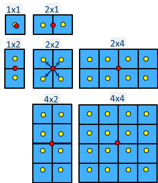
Figure 2. Intel supports the shading rates in the image above. The DirectX 12 VRS specification only requires the support of the 1x1, 2x1, 1x2, and 2x2 shading rates, but we also support the optional 2x4, 4x2, and 4x4 shading rates. The red dot denotes where the pixel shader evaluation occurs within the coarse pixel shader, then broadcasts that result to the yellow positions in the render target assuming a fully covered coarse pixel.
What is Variable Rate Shading?
Variable Rate Shading is the ability to specify the pixel shader invocation rate separately from the render target resolution and rasterization rate. VRS allows us to vary the number of times that pixels are shaded within a localized region. In our implementation we support reducing the shading rate in both the X and Y directions by two or four times, as demonstrated in Figure 2. The X and Y dimensions can be controlled separately allowing us to go beyond the basic shading rates to support an extended set including 1x2, 2x1, 2x2, 2x4, 4x2, and 4x4. The optional shading rates in the DirectX* 12 Variable Rate Shading specification include 2x4, 4x2, and 4x4. (Microsoft 2019b )12
As Figure 3 shows, we modified the multithreading sample from the Microsoft DirectX 12 SDK samples to leverage VRS on select geometry distant from the camera. At a distance, it is difficult to discern the reduced shading rate of objects. By taking advantage of this, we can improve the performance of our application without any perceivable loss in quality.
Figure 4 shows an example VRS level of detail (LOD) from a scene in Crytek* Sponza.4
Figure 3. We modified the multithreading sample in the Microsoft DirectX 12 SDK Samples to leverage VRS on select geometry distant from the camera. At a distance, it is difficult to discern the reduced shading rate of objects. By taking advantage of this we can improve the performance of our application without any perceivable loss in quality.
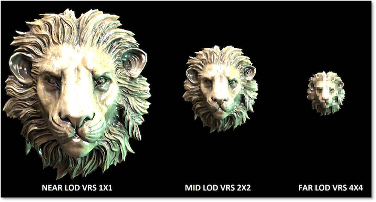
Figure 4. Example VRS Levels of Detail (LODs) from Crytek* Sponza scene.4
The Importance of Variable Rate Shading
At the time of the original publication on Coarse Pixel Shading, Intel predicted that display densities at 1080p and above would be common in consumer platforms and this is the reality today. However, the raw performance of current GPUs is not always able to keep up with the execution throughput required to shade the number of pixels in current displays. VRS is an important member of a class of rendering techniques that seeks to deliver high quality visuals by giving more control of where the shading rate can be reduced while maintaining the visual fidelity of a scene.
Software Techniques to Improve Frame Rates When Pixel Bound
Before describing the details of VRS, we want to first summarize a few software techniques in use today that reduce pixel shading requirement employed by game engine architects. Two of these methods mentioned are Dynamic Resolution Rendering (DRR) and Checkerboard Rendering (CBR).
DRR can be summarized as rendering to off-screen a variable sized render target whose dimensions can vary from frame to frame and then scaling that dynamic render target to the final fixed size frame buffer for display. In our updated DirectX 12 implementation we take advantage of placed resources to simplify the implementation and eliminate the burden of having to deal with the rightmost and bottom edge filter clamping that needed to be done in the previous implementation. We updated the original implementation by Binks (2011) and presented this work at SIGGRAPH* 2018 with a blog describing these upgrades to the original paper (Mcferron and Lake 2018a, Mcferron and Lake 2018b).9, 10
CBR is a technique inspired by other game developers’ previous work in the field (De Carpentier 2017, El Mansouri 2016, Wihldal 2017).1, 8, 15 Our implementation composites two 2xMSAA images at quarter resolution (half resolution in both height and width) in a resolve phase that includes a reconstruction algorithm that works to recover objects that were not visible in both frames. The MSAA surfaces give us more depth and coverage samples than DRR, helping to improve the quality around the edges of geometry.
Since both implementations were done in a branch of Microsoft DirectX 12 MiniEngine, we were able to combine these techniques for even better performance, being careful to choose render target sizes that were amenable to having DRR and CBR combined. If you are interested in these software-based techniques, we recommend you consult the references for additional details and performance results. They are available today in open source and have been tested to run across integrated and discrete PC GPUs.
Limitations of Software Techniques
The software techniques described previously provide a great deal of flexibility on today’s hardware. DRR is flexible and easy to integrate into an existing rendering solution, however it has a few downsides. Most importantly, the number of color, depth, and coverage samples are 1:1 with the DRR render target and we must up-sample and filter the render target to the display resolution which has the potential to introduce blur. In practice we see good results with this technique when the render target is 70 percent or greater of the render target resolution.
As described earlier, our CBR implementation uses two jittered 2xMSAA quarter resolution surfaces with the same viewport from two back to back frames to reconstruct the scene. These jittered samples provide a higher quality than two half-resolution uniform sample pattern images. Additionally, we introduce a reconstruction phase that also works to recover objects under motion. Since we have two frames of information we are effectively maintaining the same total number of samples at the cost of a reconstruction shader. Our current open source implementation achieves a 1.18 times speedup versus 1080p native resolution when rendering the Sponza scene in MiniEngine or an improvement of about five ms per frame versus native rendering.
Overcoming deficiencies in the software solutions motivates us to consider hardware-based techniques to reduce overall pixel throughput requirements, but it does not exclude using them together.
Hardware Techniques to Improve Frame Rates When Pixel Bound
While the previously described software techniques are valuable for developers, we can achieve even better performance and quality with hardware accelerated techniques. To this end, GPU vendors and researchers are working on hardware features to better utilize shading resources when rendering performance cannot meet the needs of content creators. Techniques such as adaptive multi-frequency shading (Clarberg, 2014), alongside Variable Rate Shading and multi-rate shading (He, 2014), have also been published.2, 6
VRS improves performance by reducing the rate of shading while keeping more of the coverage and depth information per pixel of the render target relative to the software techniques described previously. This means shading resources are spent where they are needed the most.
Ways to Control Variable Rate Shading Rates
As Vaidyanathan et al. (2014) describes, there are a few ways we may control the shading rate:14
- Set a VRS rate for subsequent draw calls. This can be updated multiple times per frame.
- Create an input mask that is used to read the VRS rate for a given region of the screen. This mask can be imagined as an overlay image on top of the image we are creating in the framebuffer. This is known as Tier 2 VRS and is currently not supported on 11th generation Intel® Processor Graphics Hardware.
- Use a parametric description that is evaluated at each region of pixels to determine the VRS rate. This is most often associated with describing a foveal region for use in VR and other scenarios. The VRS API does not currently support this mode. If you are interested, contact us to discuss the use of the Intel Foveated Mode extension. Observe that in the second method parametric foveated mode can be simulated with a proper image mask.
- Set a VRS rate for every vertex in the scene and optionally interpolate the value across the polygon.
- Combine these modes with a user defined function.
The 11th generation Intel Processor Graphics implementation today supports the above listed bullet points one, and three. It also supports the Microsoft variable rate shading Tier 1 specification released as part of Windows 10 19H1 which is the API we use for the functionality test application included with this whitepaper. This API provides all the flexibility required to support many VRS use cases.
Use Cases for VRS
Although the enabling of VRS is in an early stage, the hardware and APIs that are beginning to appear can give us real performance benefits. We want to explore the following areas and determine where game developers can get the most benefit. We describe some of our early results in the SIGGRAPH 2019 talk in the references.
- Objects at a distance: Objects far away from the camera may not need as much detail as objects nearer to the camera relative to if the same object was positioned closer to the viewport, particularly when they are obscured by fog or atmospheric effects.
- Objects under motion: It can be difficult to discern details in shading complexity for objects undergoing motion because they appear blurred to the human visual system; thus, expensive GPU cycles are effectively wasted on visual fidelity the user isn’t going to see.
- Objects undergoing blur or visual distortion: Engines use any number of techniques to realize the artistic intent of the game experience. Motion blur, bokeh effects, heat caustics, fog, and other atmospherics will blur or distort the image content. If we know beforehand the content we will render is going to be distorted by such effects, we can lower the visual fidelity. The saved pixel shader execution time can be spent on other pixels or recouped as an overall frame rate improvement.
- Objects in user’s visual periphery: The foveal region is a region around the center of the eye of about 5 degrees (Guenter, et al. 2012). The human visual system does not discern the details outside of this region; therefore, it can be counterproductive to spend time rendering high detail in this region. If we can track the eye we can know where the user is looking and set up our rendering pipeline to spend most of the rendering time in the foveal region and less in the periphery. Even without an eye tracking scenario, it can be valuable to concentrate rendering in specific regions of the screen by tagging regions as high importance and rendering the appropriate scene subsets with the foveal parameters. In this case the artist may also select a VRS bias for objects or materials that they know may be less relevant.
- Objects known to have slow varying lighting parameters: Some scenes, for example a stylistic cartoon theme, contain objects that have parameters that vary smoothly across many pixels. These are perfect candidates for VRS. In fact, without VRS we are over-shading as an artifact of the hardware implementation where we cannot locally control the pixel shading rate.
- Dynamic Resolution Rendering: VRS can be used in a dynamic resolution rendering scenario where we fix the foveal region to the center of the screen at a high resolution and then reduce the resolution and size of the foveal region to maintain a target frame rate. If you are not hitting the target, work to achieve a target frame rate by reducing the size of the foveal region. When you are exceeding the target, increase the foveal region.
- Power savings: When computing fewer color values relative to screen size over a naïve per pixel approach we can save power. This can be important in mobile scenarios where battery life is a factor.
Using the VRS API in Applications
Before you begin using VRS, make sure it is supported on the platform. The code segments below show how to query the platform for its level of VRS support. VRS is only on Windows® 10 Release 19H1, also known as Windows 10 Version 1903 and above, and can only be used on hardware that supports VRS. To build the sample requires the latest Windows SDK to be installed. This sample has been verified to compile with Microsoft Visual Studio* 2017.
VRS can be enabled for a specific draw call or a code region in your renderer by following these steps:
- Setup: Modify your command list to be instances of ID3D12GraphicsCommandList5. ID3D12GraphicsCommandList5 has the proper function table to set the VRS raster states during rendering.
// Modify ID3D12GraphicsCommandList to use ID3D12GraphicsCommandList5
// ComPtr<ID3D12GraphicsCommandList> m_commandList; // Does not support VRS Tier 1
ComPtr<ID3D12GraphicsCommandList5> m_commandList; // Supports VRS Tier 1
- Initialization: Check for compatibility with Tier 1 when you start your application. This will ensure we only make VRS specific calls on platforms that support VRS.
// Declare struct to store feature data.
D3D12_FEATURE_DATA_D3D12_OPTIONS6 options;

// Request Supported Features from D3D12 Device.
m_device->CheckFeatureSupport(D3D12_FEATURE_D3D12_OPTIONS6, &options, sizeof(options));

// Check for VRS Tier 1 Support or Use Fallback.
if(options.VariableShadingRateTier >= D3D12_VARIABLE_SHADING_RATE_TIER_1)
{
    // Variable Rate Shading Tier 1 Supported
    m_VRSTier1Enabled = true;
}
else
{
    // Variable Rate Shading Tier 1 Unsupported
    m_VRSTier1Enabled = false;
}
Also, query to verify support for the additional shading rates. Intel supports the extended set of VRS rates including 2x4, 4x2, and 4x4. 11th generation Intel Processor Graphics supports these additional shading rates so be sure to take advantage of them in your application on Intel® platforms.// Additional Shading Rate Check if(options.AdditionalShadingRatesSupported == true) { // Additional Shading Rates are Supported } else { // Additional Shading Rates are Unsupported }
- Per Frame or Per Draw: To change the shading rate, set it with a call on the command list
// Call RSSetShadingRate from ID3D12CommandList5 with the appropriate shading rate.
if(m_VRSTier1Enabled == true)
{
    m_commandList->RSSetShadingRate(D3D12_SHADING_RATE_4X4, nullptr);
}
The shading rates are defined with the D3D12_SHADING_RATE enumeration:
enum D3D12_SHADING_RATE
{
    D3D12_SHADING_RATE_1X1 = 0x0, // No change to shading rate
    D3D12_SHADING_RATE_1X2 = 0x1, // Reduces vertical resolution 2x
    D3D12_SHADING_RATE_2X1 = 0x4, // Reduces horizontal resolution 2x
    D3D12_SHADING_RATE_2X2 = 0x5, // Reduces both axes by 2x
    D3D12_SHADING_RATE_2X4 = 0x6, // Reduce horizontal res 2x, vertical by 4x
    D3D12_SHADING_RATE_4X2 = 0x9, // Reduce horizontal res 4x, vertical by 2x
    D3D12_SHADING_RATE_4X4 = 0xA, // Reduces both axes by 4x
};
Note that 2x4, 4x2, and 4x4 are part of the additional shading rates and not all platforms will support these.
- Per Frame or Per Draw: When finished drawing at a specific shading rate you can reset the shading rate by calling RSSetShadingRate with D3D12_SHADING_RATE_1X1.
Avoid a performance penalty by invoking RSShadingRate in the widest possible scope or sort draw calls by shading rate to avoid changing the raster state too frequently.// Call RSSetShadingRate from ID3D12CommandList5 to reset your shading rate. if(m_VRSTier1Enabled == true) { m_commandList->RSSetShadingRate(D3D12_SHADING_RATE_1X1, nullptr); }
- Normally, closing the application would require tearing down some infrastructure, but in the case of VRS there are no live objects that need destroyed or memory freed. It really is that easy.
Limitations of Tier 1 VRS
Tier 1 VRS has a few known behaviors that application developers should be aware of when using VRS:
- If SV_Coverage is declared as a shader input or output for VRS Tier 1 then the shading rate is reduced to 1x1.
- SampleMask is required to be a full mask. If SampleMask is configured to be something else, the shading rate will be reduced to 1x1.
- EvaluateAttributeAt[Centroid|Sample|Snapped] are not compatible with tier 1 VRS. If these intrinsic functions are used the shading rate is reduced to 1x1.
For 11th generation Intel Processor Graphics, we recommend minimizing shading rate changes. The current implementation requires a partial pipeline flush between shading rate changes. Be sensible about grouping objects with similar shading rates to get the best performance without introducing unnecessary overhead.
VRS Questions and Answers
This section provides answers to a few common questions. We also encourage you to review the SIGGRAPH 2019 presentation cited in the References section.
How Does MSAA Interact with VRS?
While there are some limitations with MSAA, it can be used with VRS. MSAA will continue to sample coverage and depth at the MSAA sample rate, but shading samples will be at the specified VRS rate. SV_Coverage can be used (it will not fail compilation or throw an error) with VRS, but if it is used in a shader, the shading rate will be reduced to 1 x 1.
How Does VRS Change the Mip-Map LOD Selection?
The mip-map selected with VRS is reflective of the larger pixel size, therefore the mip-map selected will move towards a lower resolution mip level to reflect the coarser resolution pixel. This can be adjusted if a higher or lower quality mip-map is desired within High-Level Shader Language (HLSL) using SampleBias() (Microsoft, 2019).13
What About Specular Aliasing?
Moving to a coarser pixel resolution can exacerbate specular highlighting artifacts or popping that developers may have worked hard to minimize before VRS integration and is dependent upon the implementation details. Filters might need updated to consider the lower resolution pixels.
Variable Rate Shading in Practice
This sample application demonstrates how to use the VRS API. It runs on 11th generation Intel Processor Graphics as well as NVIDIA Turing* architecture and shows objects under motion. The application uses VRS as part of a level of detail system. This is available on Github*.
Figure 5 and 6 demonstrate the use of the DirectX 12 VRS API on 11th generation Intel Processor Graphics.
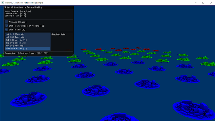
Figure 5. A simple functional sample, adapted from the Microsoft DirectX 12 Samples.
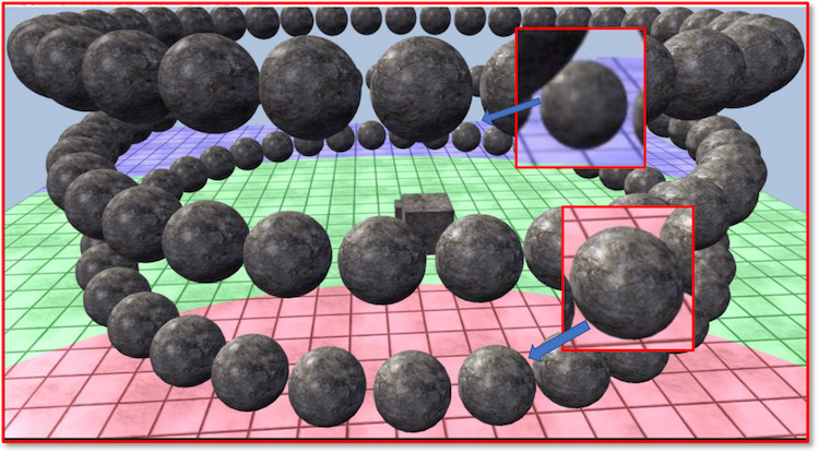
Figure 6. A scene of spheres animated to rotate around the middle of the ground plane with two different zoomed in spheres with rates of 1x1 (near the camera) and 4x4 (away from the camera). In practice one would have the transitions happen far enough away from the camera and obfuscated by atmospheric effects that any popping of the pixel rate should not be noticeable, we discuss this work in the previously referenced SIGGRAPH 2019 Presentation.
Acknowledgements
We thank Javier Martinez for getting us started; Stephen Junkins for early review; Mike Burrows, Dave Astle, Josh Doss, and Radoslav Vecera for remaining supportive of the work; Adam Kunka on the driver team for being responsive to our questions, Chuck Lingle for encouraging our work; Kai Xiao for generating new ideas and helping solve hard technical issues; and Karthik Vaidyanathan and the VTT ART Team for the first publication and hardware initiatives to breathe life into Coarse Pixel Shading. Also, Mark Dabrovic for the Sponza model.
References
- Giliam de Carpentier, Kohei Ishiyama, Advances in Real-Time Rendering in Games Course: Decima Engine: Advances in Lighting and AA, (SIGGRAPH*, 2017)
- Petrick Clarberg, Robert Toth, Jon Hasselgren, Jim Nilsson, Tomas Akenine-Moller, AMFS: Adaptive Multi-frequency Shading for Future Graphics Processors, (SIGGRAPH, 2014), vol. 33(4).
- Ian Cutress, Intel’s Architecture Day 2018: The Future of Core, Intel GPUs, 10nm, and Hybrid x86, (Dec. 12, 2018)
- Crytek* Sponza Scene, (Cryteck, 2018)
- B. Guenter, M. Finch, S. Drucker, D. Tan, J. Snyder. Foveated 3D Graphics. ACM Transactions on Graphics (2012)
- Yong He, Yan Gu, and Kayvon Fatahalian, Extending the Graphics Pipeline with Adaptive, Multi-Rate Shading. ACM Transactions on Graphics, 3, 4 (2014). 142:1–142:12.
- Adam Lake, Filip Strugar, Kelly Gawne, and Trapper McFerron, Use Variable Rate Shading (VRS) to Improve the User Experience in Real-Time Game Engines, (SIGGRAPH, 2019)
- Jalal El Mansouri, Rendering Rainbow Six Siege. (Game Developer’s Conference, 2016)
- Trapper McFerron and Adam Lake, Checkerboard Rendering for Real-Time Upscaling on Intel Integrated Graphics, (2018)
- Trapper McFerron and Adam Lake, Dynamic Resolution Rendering Update for Microsoft DirectX* 12, (2018)
- Variable Rate Shading: a scalpel in a world of sledgehammers, (March 18, 2019)
- DirectX Specs: Variable Rate Shading
- Texture2D: SampleBias methods
- Karthik Vaidyanathan, Marco Salvi, Robert Toth, Tim Foley, Tomas Akenine-Möller, Jim Nilsson, Jacob Munkberg, Jon Hasselgren, Masamichi Sugihara, Petrik Clarberg, Tomasz Janczak, and Aaron Lefohn. Coarse Pixel Shading In High-Performance Graphics. (2018 9–18.)
- Graham Wihlidal, 4K Checkerboard in Battlefield 1 and Mass Effect Andromeda. (Game Developer’s Conference, 2017)
- Kai Xiao, Gabor Liktor, and Karthik Vaidyanathan, Coarse Pixel Shading with Temporal Supersampling, I3D ’18: Symposium on Interactive 3D Graphics and Games, (I3D '18, 2018)