Introduction
3D reconstruction forms one of the basic foundational technologies for Augmented and Virtual Reality (AR and VR). At its essence, it involves understanding and replicating 3D geometry of a scene, with as much fidelity as possible. This includes capturing the shape, texture, material and other properties of the scene (Figure 1).
Capturing the essence of a scene allows for multiple applications in AR and VR. It enables realistic placement of objects in the real world, incorporating physics effects that are realistic in nature, segmenting the scene in 3D to enable object replacement – these are some examples of applications in AR. In VR, reconstructing the world allows players to avoid real world obstacles for collision avoidance.
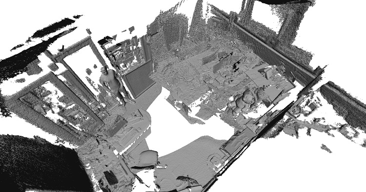
Figure 1. Reconstructing a room at a moderate level of detail using 3D reconstruction
Large scale dynamic 3D reconstruction
3D Reconstruction, as a technology, is influenced by the resolution and scale of the volume we want to reconstruct - and this determines the compute and memory bandwidth required. Resolution is determined at a voxel level (a unit of volume in space, just like a pixel is for 2D images) – it can be anywhere from a few millimeters to a few centimeters. Typically, this is also referred to as sparse and dense reconstruction - for the purpose of this white paper, we consider reconstruction at greater than 4cm to be sparse. Table 1 highlights some of the resolution requirements for different AR and VR applications, along with the performance required from the reconstruction to feed into an application or game engine. Figure 2 shows a sample reconstruction of a couch at two different resolutions.
Table 1. Typical applications of large scale reconstruction at different resolutions
| Voxel Resolution | MR Use Case | Meshing |
|---|---|---|
| > 4 cm | Obstacle Detection [Static and Dynamic] Lighting Estimation | 3-5 fps, VGA Offline, VGA |
| 1 cm - 4 cm | Social Avatar |
30 fps, 720p+ |
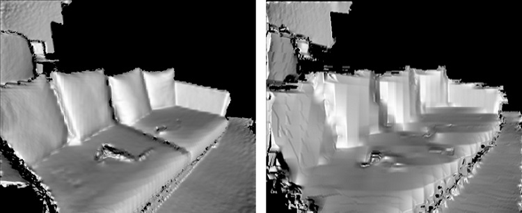
Figure 2. Sample reconstructions at 4cm (left) and 8cm (right) resolutions
The other vector of influence is the scale of reconstruction. Reconstruction can be at object scale, room scale or world scale. World scale AR and VR experiences, in addition to large scale reconstruction, require the user to be untethered in the environment and requires the system to be able to track the user continuously, using techniques like Inside out 6DoF (Engel, 2015).
Dynamic reconstruction, as per our definition, refers to building and updating a large 3D volume map continuously (Figure 3). This allows non-static objects in the scene to be continuously reconstructed – as opposed to doing a static scan of the scene beforehand and loading the volume map into the application.
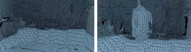
Figure 3. Dynamic reconstruction, with a person moving into the view
Key takeaways from this white paper
The rest of this white paper is intended to provide the audience with the following key takeaways:
- Develop an understanding of a large scale reconstruction pipeline
- Identify optimization opportunities on Intel platforms and their trade-offs on performance to run on Intel CPU and Graphics
- Discuss the performance of a large scale reconstruction pipeline on x86 platforms
- Decompose two example applications in VR and AR based on the pipeline
Intel Sample 3D Reconstruction Framework
High level architecture
A basic architecture flow for 3D reconstruction is shown in Figure 4.
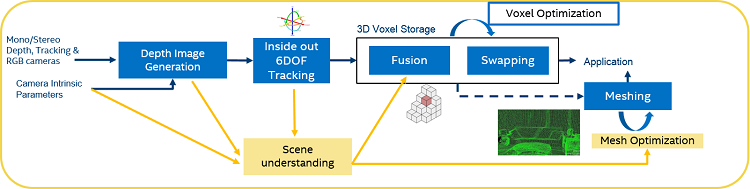
Figure 4. 3D Reconstruction pipeline
The reconstruction pipe consists of monochrome or stereo cameras (active or passive) and an RGB camera being fed into a depth generation block. The selection of cameras plays an important role in the quality of reconstruction, as shown in Table 2.
Table 2. Camera Configurations for Reconstruction
| Type of Sensor | Application | Typical Specification for CSI-2sm Imaging Sensors | System Design Consideration |
|---|---|---|---|
| Tracking Sensor | Inside out 6DoF | WFOV, Fish Eye, Global Shutter, Monochrome, > 120 fps, > 720p | Wider FOV than display to track in periphery |
| Depth Sensor | 3D Reconstruction, Semantic, Gestures | Active vs Passive, up to 1080p at 30 fps, 0.3 m-5 m, few mm error | Independent of tracking sensor |
| RGB Sensor | Texture, See-through Mode | Up to 13 MP at 30 fps for high texture Match Display Resolution and fps for See-through Mode (trending 4K at 120 fps) |
Configurable ISP processing for simultaneous high quality texture and video see-through |
Depth data along with the corresponding correlated RGB data is then fed into a SLAM (Simultaneous Localization and Mapping) module, which tracks the position of the camera with respect to an origin or reference in space. This enables a large scale VR and AR experience, as the system is not restricted to a small fixed 3D volume as is found with outside in tracking systems. The Intel® RealSenseTM Tracking Solution V200 provides such a capability for integration into VR and AR HMDs.
The depth, RGB and positional information is then fed into a fusion and meshing block. The Intel sample large scale dynamic reconstruction framework is based on a foundational technology developed by InfiniTAM (Prisacariu, 2017) and (6d.ai, 2018), which is ported to the x86 platform. The fusion block uses a hash map to store the surface properties of the reconstructed volume using Truncated Signed Distance Function or TSDF (Werner, 2014), while the meshing engine tesselates these voxels to represent them as triangles for consumption by game engines, using an algorithm like marching cubes (Lorensen, 1987). These key blocks are explained in further detail below. Significant optimization opportunities also exist at different portions of the pipeline, which are also discussed below.
Voxel hashing on PC platforms
The key to a large scale reconstruction is the ability to store and retrieve voxel data efficiently with a data structure. There are three broad methods to do this (Figure 5).
- Voxel Grid: This represents all the information in a volume by a fixed 3D grid of voxels that is pre-allocated in memory. While this results in a constant access time for each voxel to store and retrieve its TSDF values, the fact that the memory has to be pre-allocated makes it impractical to store large volumes, which can run into tens of gigabytes even for a decent sized room.
- Octrees: This is a tree based data structure where the space is sub divided recursively as octants of voxels at different resolutions. The advantage here is that the volume can be allocated as and when needed, thus making it more memory efficient.
- Hash Map: This represents the volume as a hash map, with a hash function to access a voxel. As with Octrees, this allows for a dynamic allocation and management of voxels in space. Additionally, it provides the following benefits compared to Octrees
- Ability to associate and retrieve in constant time, metadata for every voxel in addition to TSDF information– for example, material or object classification property of each voxel. Octrees require extensive search for similar capability.
- Ability to break a large volume into smaller 3D grids and manage multiple local and global hash tables at different hierarchies with efficient merges and updates between them, based on the platform compute availability and application requirements.
- Ability to manage memory more efficiently as called out by authors of InfiniTAM.

Figure 5. Voxel Grid, OctTree and Hash Map representations for 3D Fusion
X86 optimizations
Opencl™ fusion and meshing
OpenCL™ versions of fusion and marching cubes based meshing provide significant performance improvements over the CPU version and provides real-time performance on Intel graphics. Shown in Table 3. is the latency comparison between the OpenMP* and OpenCL versions of fusion, view frustum meshing and ray-casting portions of the reconstruction pipe, taken on a 6th generation Intel® Core™ i7 processor and Intel® Iris® Pro graphics system with the Long_Office_Household TUM dataset (Cremers, 2013).
Table 3. Latency comparison of OpenMP* and OpenCL™ Reconstruction for a single frame
| Fusion |
Meshing |
Ray Cast |
|
|---|---|---|---|
| 4 cm - OpenMP | 32 ms | 30 ms | 160 ms |
| 4 cm - OpenCL | < 1 ms | < 5 ms | 2.4 ms |
| 5 mm - OpenMP | 197 ms | 1.5 secs | 220 ms |
| 5 mm - OpenCL | < 1 ms | < 5 ms | 6.5 ms |
Grid based meshing
Marching cubes on a voxel hash map essentially involves parsing the entire hash table and generating mesh triangles with vertices that represent the surfaces in the volume. For each hash entry in the hash table, the algorithm requires building a vertex list of neighboring voxels of the cube that it belongs to, and identifying the triangular surfaces that pass through the cube. Once the triangles and vertices of the mesh are generated, they are provided to an AR and VR application that may be based, for example, on the Unity* Framework.
Merging these triangles generated into an indexed list on a per frame basis (i.e deleting old triangles and updated new ones) and providing an updated triangle list to the game engine for physics updates is an expensive operation. One method to overcome this is by adopting a grid based approach to mesh generation. Essentially the entire volume grid is sub divided into smaller 3D grids. Marching cubes is run on those grids that a) Are in the axis aligned bounding box of the view frustum of the current camera position in the current frame b) Have at least one new or modified voxel with TSDF (Figure 6). This helps achieve real time reconstruction on Intel graphics at room scale, for consumption by AR and VR applications. Performing the meshing on a per grid basis also allows for greater parallelization on graphics Execution Units (EU).
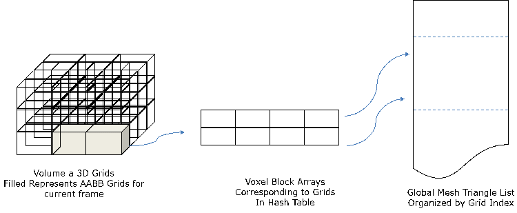
Figure 6. Performance of large scale dynamic reconstruction on x86
Mesh simplification
In order to reduce the number of triangles in every grid, a mesh simplification algorithm is run on every frame, using the modified quadric error metric algorithm . This has the potential to reduce the number of triangles by 2x-5x, thereby decreasing the load on the AR and VR application (Figure 7). By ensuring that we work on different portions of a grid, we can further parallelize the simplification using the modified QEM method on Intel graphics.
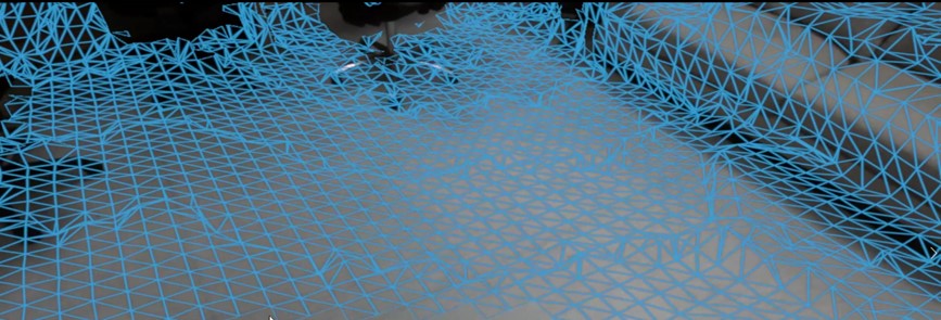
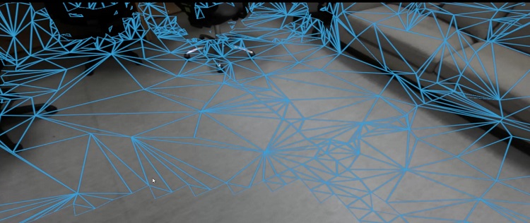
Figure 7. Meshing without (top) and with (bottom) simplification
Semantic mesh reduction
A plane detection and tracking algorithm is run on a per frame basis (Figure 8). This plane information is stored as a label on the voxel grid space using a metadata label per voxel. When running the mesh simplification per grid, an additional check is performed to see if the corresponding vertex lies on a large plane and if so the QEM algorithm is adapted to collapse the edges around the vertex more aggressively.
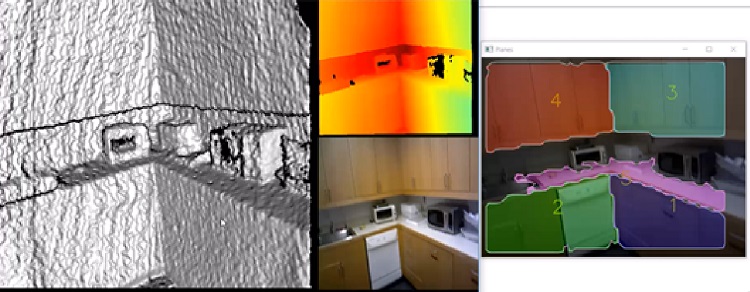
Figure 8. Plane Detection and Tracking with fusion into Voxel volume
Performance
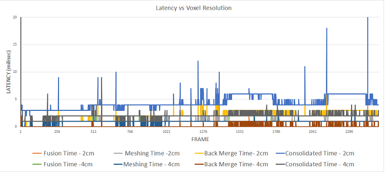
Figure 9. Performance of large scale dynamic reconstruction on x86
Figure 9 shows performance of our large scale dynamic reconstruction framework on a typical room scale dataset (x-axis shows the number of frames), taken on a 6th generation Intel® Core™ i7 processor and Intel® Iris® Pro graphics. The total time (in milliseconds) is split into three parts – time to fuse the depth data into the volume hash map, time to mesh all 3D grid of voxels in the volume that have been changed since the last update and finally, the time to merge an array of mesh objects into a AR and VR application framework like Unity. This shows that real time performance is possible on an x86 PC running an OpenCL™ optimized large scale dynamic reconstruction. The spikes seen are portions in the dataset with sudden changes in the viewpoint of camera or texture of objects in the scene.
Figure 10 shows the number of triangles for this dataset that was generated over time, without mesh simplification or semantic mesh reduction. The number of local triangles is updates since the last change, while the number of global triangles is updates within the overall volume.
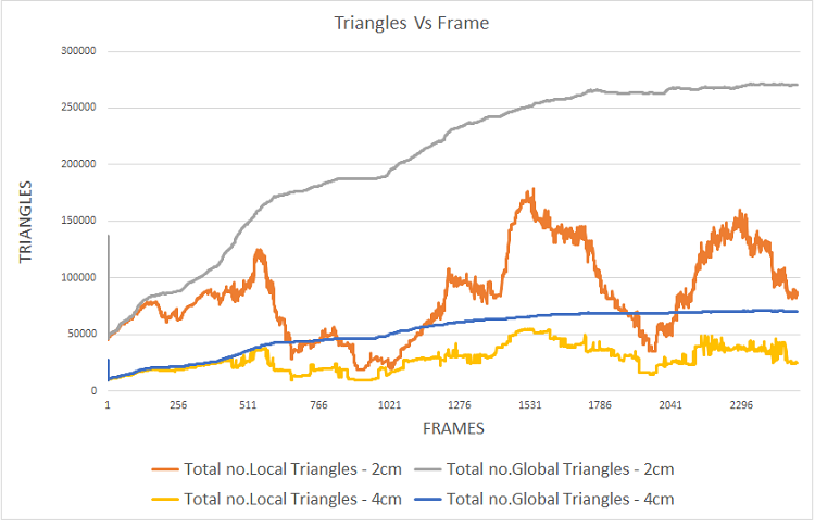
Figure 10. Number of triangles meshed in per frame and entire volume for a dataset
Figure 11 shows the savings per frame of the number of triangles before and after mesh simplification with the grid based approach, at a latency of 100-500 msecs per update.
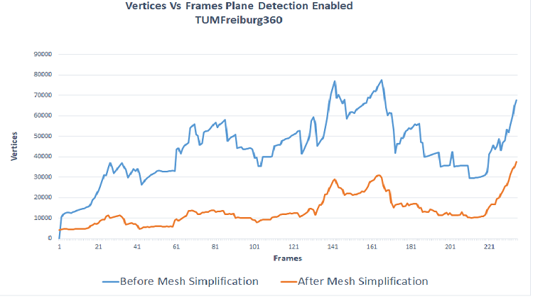
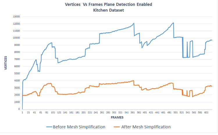
Figure 11. Mesh reduction for Kitchen and Freiburg 360 datasets (Cremers, 2013)
Example applications
Dynamic 3D reconstruction can be used to create enriching VR/AR experiences and with user safety under consideration. Below are two examples of applications of dynamic 3D reconstruction.
Collision avoidance
In non-see through 6DoF VR applications, user safety is a prime concern. With the user being ‘blind’ to world environment, physical objects in the path of movement of the user could become a potential safety hazard. Dynamic 3D reconstruction helps map the objects’ location into a unified 3D world coordinates, which then can be used to warn the user ahead of time and thus avoiding collision. And another advantage of dynamic reconstruction is that it should be able to detect when objects move, for example, a person or pet coming into the area. Figure 12 shows a graphical representation of a Collision Avoidance (CA) system intended to serve these objectives.
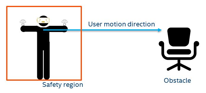
Figure 12. Collision avoidance setup
The safety region around the user can be modulated based on many factors. Some of the primary ones are the velocity of the user, velocity of the objects approaching the user etc. In a simple case, the higher the velocity of the user, the bigger the safety region should be, to provide an early warning. A preliminary user-study was conducted to find the relationship between user velocity and safety region dimensions for a particular factor of safety. The results and details of the study are beyond the scope of the white paper.
The collision avoidance application can run as a background service on a VR and AR platform, where it can send an exception to the user’s application, which can then incorporate the warning in an appropriate way (e.g. show an avatar of a cat in the room, etc.) (Figure 13).
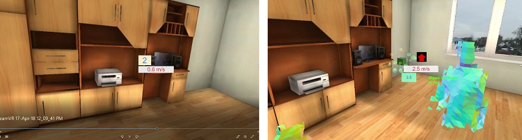
Figure 13. Left : Virtual Scene without any real world objects Right: Virtual Scene with a person approaching
Virtual object placement
Superimposing virtual objects on real-world frames in AR provides interesting user-experiences. Knowledge of planar geometric structures in 3D world coordinates helps automatically place and align virtual objects. In the simplest case, a virtual television screen can be ‘hung’ in right orientation on a planar wall in the scene with the help of large scale 3D reconstruction. The virtual TV would remain in-place even if it goes out of view, thanks to the 6DoF model of the scene.
A more complex example application could be to superimpose the moving parts of a complex machine on a real-world machine to show how they are supposed to work or move. Or completing an incomplete assembly of a complex object or machine with digital content. This would require accurately meshing the real portions of the machine and allowing the application to generate and properly place only the missing pieces.
Extending the dynamic reconstruction framework to segment and track an object can be used to extend the virtual object placement use case to dynamic objects as well.
Summary
- Large scale dynamic reconstruction is a foundational technology along with positional tracking to enable high end VR and AR experiences
- It is possible to achieve dynamic reconstruction at high resolutions with the right optimizations and partitioning on Intel CPU and graphics platforms
- Collision avoidance and virtual object placement are two lead use cases of large scale dynamic reconstruction
Call to Action: Get the best real time performance for your AR and VR applications on x86 platforms, using techniques like OpenCL optimizations and semantic understanding, and open up new application possibilities like multi-player AR and VR gaming at room scale or beyond, to generate more immersive experiences.
For more information, please contact your Intel sales representative.
Acknowledgments
The authors want to thank multiple people who contributed to the technical work or content reviews of this. Arijit Chattopadhyay and Michael D. Rosenzweig were helpful in the formulation of the problem statement and potential solutions to get high performance 3D reconstructions on Intel platforms. Mario Palumbo provided reviews and championed the work. 6A.ai provided the baseline large scale reconstruction capability on which this work was built.
References
(2018). Retrieved from 6d.ai.
Cremers, C. K. (2013). Dense Visual SLAM for RGB-D Cameras. Proc. of the Int. Conf. on Intelligent Robot Systems (IROS).
Engel, J. S. (2015). Large-scale direct SLAM with stereo cameras. International Conference on Intelligent Robots and Systems (IROS) (pp. 1935-1942.). IEEE/RSJ .
Fujiwara, T. e. (2013 ). “Plane detection to improve 3D scanning speed using RANSAC algorithm.” . IEEE 8th Conference on Industrial Electronics and Applications (ICIEA)(2013): , (pp. 1863-1869.).
Heckbert, P. S. (1999). “Optimal triangulation and quadric-based surface simplification.”. Comput. Geom., (pp. 49-65).
Lorensen, W. (1987). Marching cubes: A high resolution 3D surface construction algorithm. SIGGRAPH.
Prisacariu, V. A. (2017). “InfiniTAM v3: A Framework for Large-Scale 3D Reconstruction with Loop Closure.”. CoRR, (p. abs/1708.00783).
Werner, D. A.-H. (2014). Truncated Signed Distance Function: Experiments on Voxel Size. ICAR.
"