Introduction
This article introduces a new feature on future Intel Atom® processors to enable isolation and prioritization of code and data (individually) within the L2 cache. For specialized applications with high sensitivity to either code or data locality in the cache, the L2 Code and Data Prioritization (CDP) feature can provide performance, latency, or determinism advantages.
Intel® Resource Director Technology (Intel® RDT) Feature Set: Background
The L2 CDP feature is part of the Intel® Resource Director Technology (Intel® RDT) feature set, which provides a number of monitoring and control technologies to help software understand and control the usage of shared resources within the platform, such as last-level cache (LLC) and memory bandwidth. A set of technical articles and other resources on Intel® RDT are linked from the main landing page.
The Intel RDT feature set includes Cache Allocation Technology (CAT), which provides programmatic control over LLC data placement per application, virtual machine (VM), container, or thread, which can be used to isolate or differentiate the performance of key workloads, in particular in complex data center environments. More details on the CAT feature can be found in a series of technical articles, with the first linked here.
An extension of CAT is the CDP feature, which remaps CAT masks to enable separate masks for code and data. In prior processor generations the CDP feature has been available at the L3 cache level in the Intel® Xeon® processor family, starting with the Intel® Xeon® processor E5 v4 family. The new L2 CDP feature brings this capability to the Intel Atom processor line for the first time.
CAT and CDP Background
A number of current Intel Atom processors support CAT architecturally at the L2 cache level, providing software the ability to control usage of the cache, enabling isolation and prioritization across a wide variety of usage models.
The CAT feature relies on mapping each running thread into a Class of Service (CLOS or COS) via a per-thread MSR (the IA32_PQR_ASSOC MSR, or “PQR”), which can be context swapped by an enabled OS or Virtual Machine Manager (VMM) to differentiate between threads dynamically.
Figure 1 shows the flexible mapping possible between a thread and a CLOS.
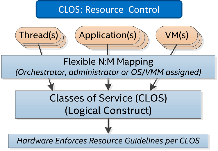
Figure 1: Each hardware thread is assigned a Class of Service (CLOS), which is assigned by the OS/Virtual Machine Manager. The same or different CLOS can be used dynamically as needed to differentiate between threads, applications, virtual machines, or containers.
Each CLOS maps into a block of MSRs (IA32_L3_QOS_MASK_n, where “n” is the corresponding CLOS) to select the associated capacity mask for the currently running thread on a core, as shown in Figure 2.
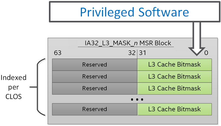
Figure 2: Configuration of the L3 Capacity Bitmasks (CBMs) per logical Class of Service (CLOS), via the IA32_L3_MASK_n block of MSRs, where n corresponds to a CLOS number.
The assigned cache bitmasks can then be used to control the amount of cache available to threads in a given CLOS, where set bits indicate the ability to utilize an assigned region of the cache.
The CDP feature extends CAT by remapping masks to enable separate control over code and data placement in the cache. Each CLOS is remapped to have two masks, one for code and one for data, and the total number of mask MSRs is effectively cut in half.
When CDP is enabled the existing mask space is re-indexed to provide separate control over code and data, as shown in Figure 3.
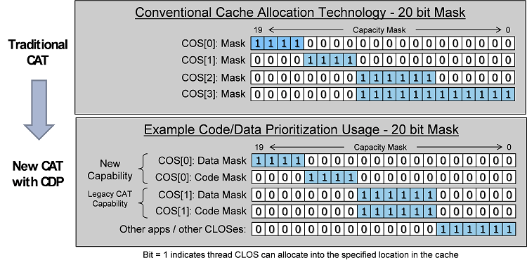
Figure 3: Code and Data Prioritization (CDP) mask details: when enabled, one mask is provided for code, and one for data for each CLOS.
As shown in Figure 3, CDP provides separate control over code and data by enabling separate masks for code and data. With traditional Cache Allocation Technology enabled, Classes of Service map 1:1 with capacity bitmasks (CBMs). With CDP enabled the mapping is now 1:2 (each CLOS maps to two CBMs, one for code and one for data).
The new L2 CDP feature provides separate control over code and data at the L2 cache level. Enumeration, configuration, and usage details are provided in the next section.
L2 CDP Interface Details: Enumeration, Configuration, and Usage
L2 CDP is an extension of the L2 CAT feature. Once the presence of the L2 CAT feature has been confirmed (via CPUID.(EAX=07H, ECX=0):EBX.PQE[bit 15] and CPUID.(EAX=010H, ECX=0), see the Intel software developer’s manual for details) the L2 CDP feature can be enumerated.
The presence of the L2 CDP feature is enumerated via extensions to the L2 CAT CPUID sub-leaf, specifically CPUID.(EAX=10H, ECX=2):ECX.CDP[bit 2] (see Figure 4).
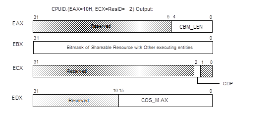
Figure 4: Figure 4. CPUID.010H.02H Sub-Leaves for L2 CAT and L2 CDP Details. The CDP bit above in the ECX register enumerates the presence of CDP, and the remainder of the fields are described in detail in the Intel software developer’s manual.
Most of the CPUID.(EAX=10H, ECX=2) sub-leaf data that applies to CAT also apply to CDP. However, CPUID.(EAX=10H, ECX=2):EDX.COS_MAX specifies the maximum COS applicable to CAT-only operation. For CDP operations, COS_MAX_CDP is equal to (CPUID.(EAX=10H, ECX=2):EDX.COS_MAX_CAT >>1).
If CPUID.(EAX=10H, ECX=2):ECX.CDP[bit 2] =1, the processor supports L2 CDP and provides a new MSR IA32_L2_QOS_CFG at address 0C82H. The layout of IA32_L2_QOS_CFG is shown in Figure 5. The bit field definitions of IA32_L2_QOS_CFG are:
- Bit 0: L2 CDP Enable. If set, enables CDP, maps CAT mask MSRs into pairs of Data Mask and Code Mask MSRs. The maximum allowed value to write into IA32_PQR_ASSOC.COS is COS_MAX_CDP.
- Bits 63:1: Reserved. Attempts to write to reserved bits result in a #GP(0).

Figure 5: Layout of IA32_L2_QOS_CFG
IA32_L2_QOS_CFG default values are all 0s at RESET, and the mask MSRs are all 1s. Hence all logical processors are initialized in COS0 allocated with the entire L2 available and with CDP disabled, until software programs CAT and CDP. The IA32_L2_QOS_CFG MSR is defined at the same scope as the L2 cache, typically at the module level for Intel Atom processors, for instance. In processors with multiple modules present it is recommended to program the IA32_L2_QOS_CFG MSR consistently across all modules for simplicity.
17.19.6.2 Mapping between L2 CDP Masks and L2 CAT Masks
When CDP is enabled, the existing CAT mask MSR space is remapped to provide a code mask and a data mask per COS. This remapping is shown in Table 1, and the same indexing pattern is used for L3 CDP feature, but for the L2 MSR block (IA32_L2_QOS_MASK_n) instead of the L3 MSR block (IA32_L3_QOS_MASK_n).
Table 1. Re-Indexing of COS Numbers and Mapping to CAT/CDP Mask MSRs.
| Mask MSR |
CAT-only Operation |
CDP Operation |
|---|---|---|
| IA32_L2_QOS_Mask_0 | COS0 | COS0.Data |
| IA32_L2_QOS_Mask_1 | COS1 | COS0.Code |
| IA32_L2_QOS_Mask_2 | COS2 | COS1.Data |
| IA32_L2_QOS_Mask_3 | COS3 | COS1.Code |
| IA32_L2_QOS_Mask_4 | COS4 | COS2.Data |
| IA32_L2_QOS_Mask_5 | COS5 | COS2.Code |
| .... | .... | .... |
| IA32_L2_QOS_Mask_’2n’ | COS’2n’ | COS’n’.Data |
| IA32_L2_QOS_Mask_’2n+1’ |
COS’2n+1’ |
COS’n’.Code |
One can derive the MSR address for the data mask or code mask for a given COS number n by:
- data_mask_address (n) = base + (n <<1), where base is the address of IA32_L2_QOS_MASK_0.
- code_mask_address (n) = base + (n <<1) +1.
As with L3 CDP, when L2 CDP is enabled, each COS is mapped 1:2 with mask MSRs, with one mask enabling programmatic control over data fill location and one mask enabling control over data placement. A variety of overlapped and isolated mask configurations are possible (see the example in Figure 3).
Mask MSR field definitions for L2 CDP remain the same as for L2 CAT. Capacity masks must be formed of contiguous set bits with a length of 1 bit or longer, and should not exceed the maximum mask length specified in CPUID. For example, valid masks on a cache with max bitmask length of 16b (from CPUID) include 0xFFFF, 0xFF00, 0x00FF, 0x00F0, 0x0001, 0x0003 and so on. Maximum valid mask lengths are unchanged whether CDP is enabled or disabled, and writes of invalid mask values may lead to undefined behavior. Writes to reserved bits will generate #GP(0).
L2 CDP Software Considerations
Before enabling or disabling L2 CDP, software should write all 1s to all of the corresponding CAT/CDP masks to ensure proper behavior (for example, the IA32_L2_QOS_Mask_n set of MSRs for the L2 CAT feature). When enabling CDP, software should also ensure that only COS numbers that are valid in CDP operation are used, otherwise undefined behavior may result. For instance in a case with 16 CAT COS, since Classes of Service are reduced by half when CDP is enabled, software should ensure that only COS 0‒7 are in use before enabling CDP (along with writing 1s to all mask bits before enabling or disabling CDP).
Software should also account for the fact that mask interpretations change when CDP is enabled or disabled, meaning for instance that a CAT mask for a given COS may become a code mask for a different CLOS when CDP is enabled. In order to simplify this behavior and prevent unintended remapping, software should consider resetting all threads to COS[0] before enabling or disabling CDP.
The L2 mask MSRs are scoped at the same level as the L2 cache (similarly, the L3 mask MSRs are scoped at the same level as the L3 cache).
Configuration and Usage
After verifying the presence of L2 CAT and L2 CDP (via CPUID), the mask MSRs may be set to all 1s, the L2 CDP feature may be enabled (via the IA32_L2_QoS_CFG MSR), and the masks may be further configured into code/data masks. Key threads, applications, VMs, and containers of interest may then be assigned into Classes of Service as needed, with per-thread hardware and software associations maintained by the OS or VMM at context swap time with the IA32_PQR_ASSOC MSR.
Conclusion
The new L2 CDP feature enables programmatic control over code and data placement in the L2 cache for future Intel Atom processors. This new capability builds on the L2 CAT feature on certain Intel Atom processors, enabling new capabilities and advanced platform tuning opportunities for uses including industrial, motion control, communications, networking, digital signage and the Internet of Things.
While this article provides an early overview of the features and technical details on the enumeration and interfaces, software enabling and support is planned through Intel’s Software and Services Group, including the Open Source Technology Center (OTC), and enabling patch links will become available in the near future.
"