Download PDF 957KB
This article describes the Data Plane Development Kit (DPDK) Packet Framework, which allows rapid prototyping of real-world packet processing workloads on multicore Intel® CPUs with great flexibility and performance. This framework is based on three DPDK libraries: librte_port, librte_table, and librte_pipeline.
The DPDK Packet Framework library was first introduced in DPDK v2.1 along with a reference application known as ip_pipeline. In subsequent releases, various features were added to the ip_pipeline application to transform it into a toolbox for developing complex packet processing workloads such as edge routers. The information here applies to DPDK versions 16.04 and above.
Packet Framework Library
The DPDK Packet Framework employs a suite of DPDK libraries (librte_port, librte_table, and librte_pipeline) to define a standard methodology for building complex packet processing applications. It provides reusable and extensible templates for building various functional application blocks as pipeline modules.
Each pipeline module is constructed of three primitive entities: input ports, output ports, and tables. An example is shown in Figure 1.
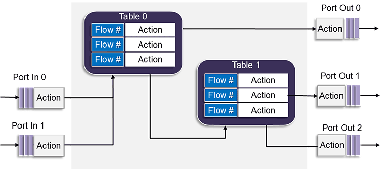
Figure 1. The DPDK Packet Framework.
Input ports can only be connected to one table; however, that one table can be connected to other tables and also to output ports.
Various actions can be performed on packets as they traverse the pipeline blocks. For example, packet header integrity and verification can be performed at an input port. In addition, table actions can be applied, based on the result of a look-up operation, to forward packets to another table, to send packets to an output port, or to simply drop the packets.
The IP Pipeline Application
The IP Pipeline application is designed to demonstrate the use of the DPDK Packet Framework tool suite. This sample application, in the DPDK codebase, provides the following data plane functions implemented using the above pipeline model.
- Pass-through Pipeline: This pipeline offers a cable-like connectivity between its input ports and output ports and is typically used to adapt a set of ports from one type to another. This pipeline is basically a placeholder for implementing various functions such as load balancing or computing metadata required at subsequent packet processing pipeline stages.
- Flow Classification Pipeline: This pipeline connects all the input ports to a table that classifies the packets based on a hash lookup and sends them to the matching ports. Different types of packets such as QinQ, IPv4, and IPv6 can be classified using this pipeline.
- Routing Pipeline: This pipeline employs a longest prefix match (LPM) table to route the incoming packets. If fast path address resolution protocol (ARP) (implemented using a hash table) is enabled in the pipeline, the output port is determined on the basis of LPM and ARP table lookups. Depending on the next hop protocol, the packet can also be encapsulated with a QinQ header or multiprotocol label switching (MPLS) labels.
- Firewall Pipeline: This pipeline uses an access control list (ACL) table to implement firewall policies on the incoming traffic.
- Flow Action: This pipeline performs two operations:
- Ingress traffic metering/marking by assigning colors to the packets as a measure of how much the user/flow currently exceeds its pre-allocated bandwidth.
- Traffic policing by enforcing predefined actions on the input packet based on the assigned color.
Theses pipelines can be seen as prefabricated blocks that can be instantiated and interconnected by means of a configuration file to create complete applications.
The application configuration file defines the application structure that includes pipeline instances, device queues, and software queues. Different applications are created by using different configuration files; therefore, the ip_pipeline sample application can be seen as an application generator. The configuration of each pipeline can be updated at run time through the application's command-line interface (CLI).
Running the IP Pipeline Sample Application
The following steps are required to run the DPDK Packet Framework-based ip_pipeline sample application.
- Go to the ip_pipeline application directory:
$ cd /home/dpdk/examples/ip_pipeline/
- Export the following environmental variables and set the required target:
$ export RTE_SDK = /home/dpdk

$ export RTE_TARGET = x86_64-native-linuxapp-gcc
- Build the ip_pipeline application:
$ make
- To run the ip_pipeline sample use a command line like the following:
ip_pipeline [-f CONFIG_FILE] [-s SCRIPT_FILE] -p PORT_MASK [-l LOG_LEVEL]
The application command-line arguments are:
-f CONFIG_FILE: (optional, default: ./config/ip_pipeline.cfg). This is the path to the configuration file to be loaded by the application.-s SCRIPT_FILE: (optional). This is the path to the CLI script file to be run by the primary pipeline at application startup. No CLI script file will be run at startup if this argument is not present.-p PORT_MASK: (required). The hexadecimal mask of the NIC port IDs to be used by the application.-l LOG_LEVEL: (optional). The log level to determine which application messages are to be printed to standard output. Available log levels are: 0 (None), 1 (High priority), and 2 (Low priority).
Example: L3 Forwarding
The usage of the pipeline blocks is demonstrated by means of several sample applications and configuration files that are provided with the ip_pipeline application.
Figure 2 shows one such configuration file for a Layer 3 (L3) forwarding application.
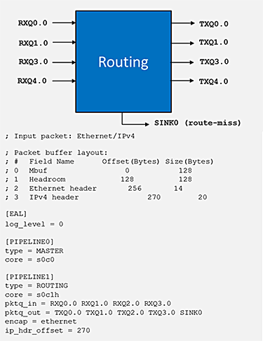
Figure 2: L3 Forwarding Application Configuration file (l3fwd.cfg).
In the file, the [PIPELINE] section defines various parameters of the pipeline. In this particular case it sets up simple routing.
The "core" entries thread id (tuple of socket ID, physical CPU ID, and hyper-thread ID) determines the CPU core to run the pipeline.
The "pktq_in" and "pktq_out" parameters define the packet transfer interface; in this case, to receive and send packets.
The "encap" parameter can be set to "ethernet", "qinq", or "mpls" to encapsulate all outgoing packets with the appropriate header.
The last parameter, "ip_hdr_offset", is used to set the offset bytes needed to offset to the start of the ip-header in the DPDK packet structure (mbuf).
Figure 3 shows the ip_pipeline script file with routing rules added to the LPM table of the routing pipeline. Entries in this file are related to the case where the "encap" field is set to "ethernet" and the fast path ARP is disabled.
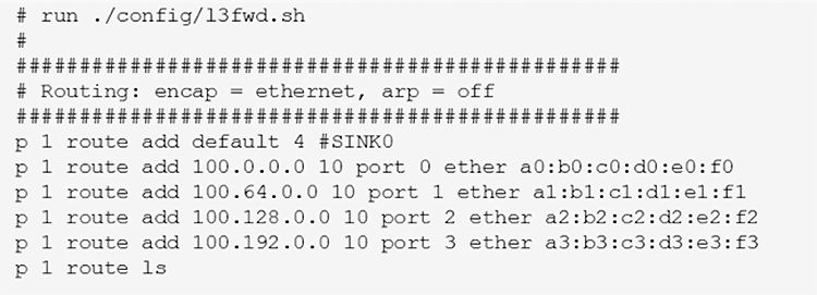
Figure 3: L3 Forwarding Application Rules file (l3fwd.sh).
The rules in the script file have the following format:
p <pipeline_id> route add <ip_addr> <depth> port <port_id> ether <next hop mac_addr>
Use the following command to run the L3 forwarding application:
$./build/ip_pipeline -f l3fwd.cfg -p 0xf -s l3fwd.sh
Visual Representation
Sometimes applications can have complex topologies in terms of interconnections between different functional blocks. In these cases it can becomes difficult to understand the application packet processing flow by simply looking at its configuration file. In order to help with this a Python* program called diagram‑generator.py has been provided to create visual diagrams of the application topology from the configuration file.
Once the application configuration file is ready, run the command shown below to generate the diagram.
$./diagram-generator.py -f <configuration file>
Figure 4 shows a section of a generated topology for a complex ip_pipeline application.
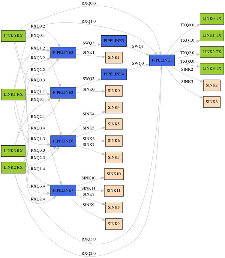
Figure 4: Section of a generated topology for a complex ip_pipeline application.
Conclusion
This article describes the DPDK packet framework library, which enables rapid prototyping of real-world packet processing applications on multicore CPU systems, and presents the architecture of the standard pipeline model built using this library.
The various network functions (pipelines) constructed using this standard pipeline model are available as part of the DPDK ip_pipeline sample application. Although some of these are simple examples, a straightforward configuration file can build realistic applications. This article presents the commands to visualize and run the applications.
Additional Information
Check out the DPDK Programmer's Guide for a full description of the DPDK Packet Framework design.
Two sample applications are provided for Packet Framework: app/test-pipeline and examples/ip_pipeline. Refer to the DPDK Sample Apps Guide for a detailed description of how these sample applications work.
About the Author
Jasvinder Singh is a network software engineer with Intel. His work is primarily focused on development of data plane functions and libraries for DPDK. His contributions include packet framework enhancements and the ip_pipeline sample application.
"