Overview
The Next Generation Infrastructure Core (NGIC) is an Evolved Packet Core (EPC) based on software-defined networking (SDN) and network functions virtualization (NFV), as part of a collaboration between Intel Labs and Sprint*. NGIC was released as part of the M-CORD (Mobile Central Office Re-architected as Datacenter) project to the Open Networking Foundation, and the code is available, hosted by OpenCORD.org. The code contains a reference implementation of the serving and packet gateways implemented as separate control and data planes. (Note that NGIC is not a product and will not be a product from Intel; it is a reference implementation designed to address and research software and hardware platform improvements.)
This hands-on demo guides you through setting up NGIC on your own machine and allows you to launch some sample traffic through the system to understand the packet flow in the reference implementation. Setup is quick and easy with Docker* containers and does not require a special traffic generator or similar testing equipment.
Background
The EPC architecture defines the core cellular network architecture as defined by the 3GPP. (There are many different components of the EPC that are out of the scope of this article, but you can read more in the 3GPP TS 23.002, which provides an overview of all of the EPC network elements.)
Some of the main network elements (see Figure 1) include:
- User equipment (UE): The device used by the end-user (such as a cell phone).
- eNodeB (eNB): The base station (or cell tower/radio), which provides the UE radio access to the network.
- Mobility Management Entity (MME): Handles mobility events such as when the UE must connect to a different eNB, and thus potentially, different core network elements.
- Serving Gateway (SGW): Serves the UE by granting access between the radio and core network.
- Packet Gateway (PGW): Exposes the core network to IP Multimedia Subsystem (IMS), which include access to the Internet, phone networks, and so on.
- IMS: Internet and telephone.
- Home Subscriber Server (HSS): A database containing user subscription data.
- Policy and Charging Rules Function (PCRF): Flow-based charging and policy enforcement.
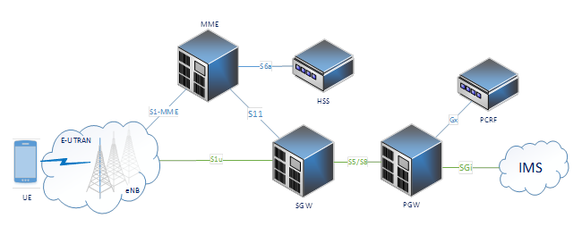
Figure 1. Current mobile network architecture (image credit: Jacob Cooper)
Our NGIC implementation of the EPC architecture (see Figure 2) focuses on independent control and data scaling in the SGW and PGW. The blue box indicates the current NGIC components. NGIC is implemented with the SGW and PGW as collapsed functionalities (or alternatively supported as separate nodes), implemented as the Control Plane (CP) and Data Plane (DP), and an optional SDN controller. The CP and DP are fully separate and virtualized.
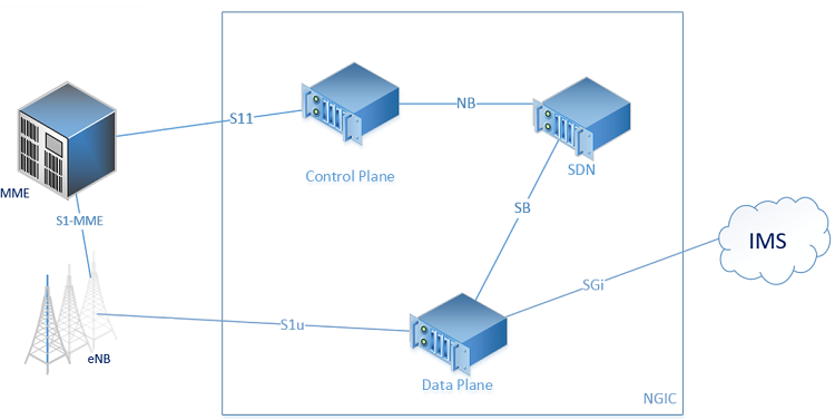
Figure 2. NGIC and the EPC (image credit: Jacob Cooper)
Currently, the three main components of NGIC are as follows:
- The CP handles the signaling messages from the MME (S11 messages) which sets up, modifies, and deletes the user sessions.
- The SDN controller (more information from Sprint) can perform additional capabilities related to Forwarding Policy Configuration (FPC) available in a repo under OpenDaylight*, which is not used in this demo. For this demo, the CP and DP communicate directly.
- The DP handles many features including metering, bearer mapping, and enforcement of policy and charging rules. It also handles the GTP-U encapsulation/decapsulation and communicates to the eNB over the S1u interface and the IMS over the SGi interface.
Additional component implementations (MME, PCRF, and HSS) are under development and are not discussed in this article.
NGIC Data Plane Details
The DP makes use of the Data Plane Developer Kit (DPDK). Figure 3 shows the packet flow through the DP.
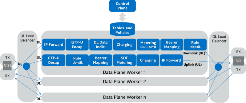
Figure 3. NGIC data plane details
Packets flow through the DP as follows:
- Packets arrive at the receive (RX) core (Figure 3, far left and far right), which polls both the S1u and SGi interfaces. Packets are then ring-buffered for the load balancer.
- The load balancers poll the ring buffer and balance packets among worker cores by the UE IP present in the packet header. Again these packets are ring-buffered.
- Each worker core polls its two ring buffers, one for uplink traffic (UL), and the other for downlink (DL) traffic.
- UL traffic goes through a series of processing steps, including packet decapsulation, rule identification, bearer mapping, charging and metering. Packets are then ring-buffered once again for transmission.
- DL traffic goes through similar processing: rule identification, bearer mapping, metering, charging, and encapsulation. DL Data Notification and buffering takes place if required. Packets are then ring-buffered once again for transmission.
- he transmission ring buffers are polled by the transmit (TX) pipeline stage, which sends the packets.
The DP uses DPDK to achieve high-performance networking on Intel® architecture.
Experimental Setup
NGIC has been tested on bare metal in virtual machines and most recently in Docker containers.
However, you can also run the NGIC software on a common laptop to test it. Since the goal of this post is to show a simple working prototype, we focus on the Docker-based setup. We provide prebuilt Docker images.
This demo requires:
- A Linux* box (bare metal or VirtualBox*) with at least 4 GB of free RAM. We recommend Ubuntu* 16.04, but the demo has been tested with various older Ubuntu (14.04) and also Fedora* (release 25) installations. (This operating system is just the host; the containers themselves will all have Ubuntu 16.04.)
- Docker* (at least version 1.13) and Docker-compose.
- Our demo files: git clone https://github.com/ngiccorddemo/cordbuild2017.git
This post only covers using the prebuilt Docker images.
If you want to build the NGIC Docker images from scratch, you will need at least Docker 17.06-ce; the instructions can be found here. They guide you through pulling the NGIC source code from Gerrit* and building it from scratch, which will allow you to modify, test, and contribute to the source code.
Getting Started
Once you have cloned the demo files in the cordbuild2017 repo as instructed above, open two additional terminals, and in all of them change directory to the demo folder:
cd cordbuild2017NOTE: If you are running this demo in VirtualBox directly or indirectly, run the following command to use the VirtualBox-specific Docker images:
## Do only if using virtualbox:
sed -i 's/latest/vbox/g' .env
Pull the Images
Use Docker-Compose to pull the images (assuming you’re not building them from scratch as noted above):
docker-compose pull cp dp trafficThis downloads three separate Docker images shown in yellow below.
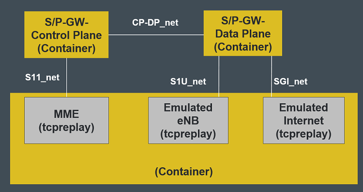
Figure 4. NGIC dockerized demo setup
The first two images, CP and DP, are built from a specific commit (a9e0575) of the NGIC source code. The third image, traffic, is a clean Ubuntu 16.04 installation with tcpreplay installed. We will use the traffic container to emulate the non-NGIC components (MME, eNB, and IMS).
To show that the images are successfully downloaded, check docker images:
~/cordbuild2017$ docker images
REPOSITORY                 TAG     IMAGE ID      CREATED     SIZE
ngiccorddemo/ngic-dp       latest  0ec485ec504d  2 weeks ago 357MB
ngiccorddemo/ngic-traffic  latest  198892fd3cb9  2 weeks ago 521MB
ngiccorddemo/ngic-cp       latest  69026e54e214  2 weeks ago 283MB
(If you are using VirtualBox, the TAG says vbox instead of latest.)
Starting the Data Plane
In the first terminal, start the DP using docker-compose:
docker-compose -p epc up dpWait until you see messages about Unable to resolve ..., which means that the DP is waiting for the other containers.
Starting the Control Plane
In the second terminal, bring up the CP with:
docker-compose -p epc up cpWait until you see messages about Unable to resolve mme.s11.ngic., which means that the CP is waiting for the traffic container.
Setting up the Traffic Container and Verifying Setup
In the third terminal, bring up the Traffic container in daemon mode (-d) with:
docker-compose -p epc up -d trafficThis command starts the container in the background. Now all three containers are started and should be able to see each other. Switch back to the first terminal (DP). You should see some outputs about RTE (DPDK’s Run Time Environment), and see some stats begin to print as follows:
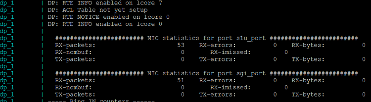
Note that it may take approximately 15 seconds for the output to show up in the terminal after all containers have been started.
The output prints information about the packets sent and received on the S1U and SGi interfaces. You may also see a few spurious packets received, which are dropped.
Switch to the second terminal (CP).
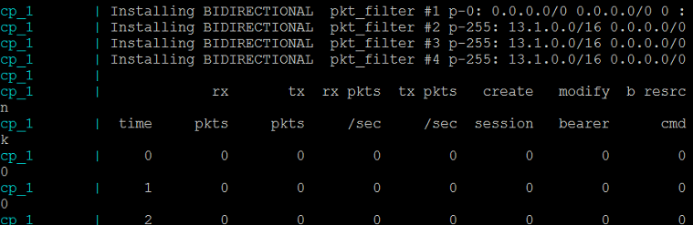
You should see a table with lots of packet counter stats, which are all 0 for now since we haven’t started any CP traffic. The CP waits for packets from the MME to install rules and set up flows on the DP.
Sending the Traffic
In the third terminal, enter the Traffic container with:
docker exec -it epc_traffic_1 /bin/bashThis gives you a Bash shell in the Traffic container.
root@ec8e7b86c1be:/opt/ngic/pcap# ls
rewrite_pcaps.py s11.pcap s1u.pcap sgi.pcap
For this demo, we included three pcap files in the Traffic container: traffic creating the sessions, the uplink traffic, and the downlink traffic. We need to update this prerecorded traffic to have the correct IP addresses based on resolving the names of the running containers. We included a Python* script that uses scapy to modify the necessary address fields. Generate three modified pcap files (this takes several seconds.):
root@ec8e7b86c1be:/opt/ngic/pcap# ./rewrite_pcaps.py enb.s1u.ngic spgw.s11.ngic spgw.s1u.ngic spgw.sgi.ngicNext, we have to figure out where Docker mapped each of the three network interfaces inside the container. If you look at the diagram (Figure 2: NGIC Dockerized Demo Setup) above, you’ll see that the Traffic container uses three different networks: S11, SGi, and S1U. Currently, Docker brings up multiple interfaces in random order, so we must run a command to determine which interface maps to which network.
Paste the following into the Traffic container:
S11_IFACE=$(ip route get $(dig +short spgw.s11.ngic) | head -1 | awk '{print $3}')
S1U_IFACE=$(ip route get $(dig +short spgw.s1u.ngic) | head -1 | awk '{print $3}')
SGI_IFACE=$(ip route get $(dig +short spgw.sgi.ngic) | head -1 | awk '{print $3}')
You can test and make sure it worked with:
root@ec8e7b86c1be:/opt/ngic/pcap# echo $S11_IFACE
eth0
root@ec8e7b86c1be:/opt/ngic/pcap# echo $S1U_IFACE
eth2
root@ec8e7b86c1be:/opt/ngic/pcap# echo $SGI_IFACE
eth1
This demo uses tcpreplay to replay prerecorded GTPv2 traffic into the CP and DP. Before we can send or receive traffic, first we need to install some rules using the CP. Play the S11 (control plane) traffic to set up the flows:
tcpreplay --pps=200 -i $S11_IFACE tosend-s11.pcapSwitch back to the second (CP) terminal. You should see that 1000 CreateSession and 1000 ModifyBearer packets were received for a total of 2000 received and 2000 sent packets:

Now start the S1U (Data Plane uplink) traffic:
tcpreplay --pps=2000 -i $S1U_IFACE tosend-s1u.pcapCheck the DP (Screen #1). You should see approximately 6500 packets received on the S1U and approximately 6500 packets transmitted on the SGi.
Now start the SGi (DP downlink) traffic:
tcpreplay --pps=2000 -i $SGI_IFACE tosend-sgi.pcapCheck the DP (Screen #1). You should see approximately 6500 packets received on the SGi and approximately 6500 packets transmitted on the S1U.
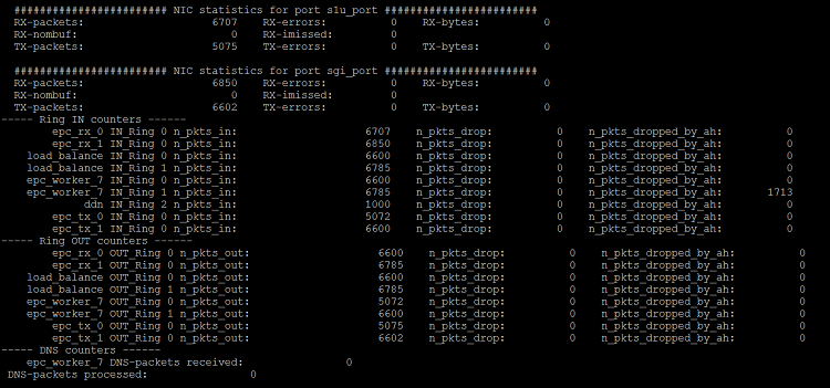
The output of the DP shows the various stages of the packets in the data pipeline that are outlined in Figure 3.
Tear Down
From the Traffic terminal, type:
exitand then type:
docker-compose -p epc down
Notes about this Demo
The sample demo above shows the overall setup and packet flow in NGIC, but it takes a real traffic generator, such as ng4t and Spirent and Ixia, to really test the performance and throughput.
Summary
This article provided an overview of NGIC and a hands-on demo for how to test containerized versions of the CP and DP using replayed traffic. Key takeaways include:
- The NGIC source code is publically available and can allow research and collaborations to test and understand telecom workloads behavior on Intel architecture.
- NGIC has separate and scalable CPs and DPs, and it uses the DPDK to optimize DP functionality on Intel architecture.
About the Author
Karla Saur is a Research Scientist at Intel Labs working on scalability in the EPC. Before coming to Intel, Karla finished her PhD in computer science at the University of Maryland. She is broadly interested in scalability and availability in distributed systems.
This article is based on a demo given at CORD Build 2017 along with Saikrishna Edupuganti and Jacob Cooper.
"